Automatic Transmission
In our lab exercise we dissembled identified its mechanical parts a three speed manual transaxle of a rear wheel drive vehicle as shown in the diagram below:

As we noticed that this rear wheel drive transaxle does not have the final drive and differential inside. The final drive and differential is connected to the transaxle with propeller shaft, which is connected to the output shaft of the transaxle. The reason we used the transaxle shown above is due to its simplicity that will give us a better understanding of automatic transmission as beginners.
First thing we did is as usual we dissembled this transmission shown above, inspected and identified its mechanical components and then resembled everything back to its original state. Dissembling process of this automatic transmission is not as hard as the manual transmission we have done previous. I think this is probably because it didn’t use many physical gear shift mechanisms; instead a hydraulically operated valve control body is used. Eventual the physical appearance of this automatic transmission but as it is using hydraulic controls and planetary gears – its operation is somehow seems to be much more complicated than manual transmission we done before. This is because its operation is a lot more abstract, we cannot understand how it works until we studied the theory behind its operation. To understand how automatic transmission there two important parts we have to understand:
Its mechanical parts – this includes clutch, bands and gearing etc.
Its hydraulic control system – the components inside the valve control body or the brain of this transmission.
We dissemble this transmission in the following order
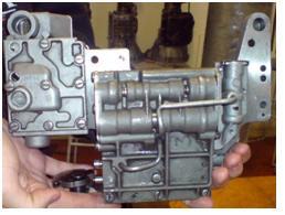
1. Turn the transmission over as shown.

1. Remove its oil pan to expose some of its components.

1. Valve body removed
As valve control is removed, more components revealed.

1. Servos are then removed, now we could sea the components more clearly.

1. Front Clutch, Rear Clutch, Front Band are then removed. With the rest of the component we have to start from the output side of the transmission. First we have to remove the output extension housing.

1. Slide governor and oil pump off from the output shaft.

1. Then the rest of the transmission components are taken out from the back and dissembling is completed. The resembling procedure is the exact opposite.
Transmission is used to control the torque output from the engine to the drive line to drive a vehicle according to the gear selected, therefore the output is controlled according to the condition. In a manual transmission gear selection is done by the driver where as this is done by mainly by valve body control in this automatic transmission we have studied in this lab exercise. There are two parts we have to look at as listed below:
l The mechanical part
l Hydraulic Control
The mechanical parts
This is the gears, Clutches and bands layout of the transmission we took apart


The automatic transmission output is varied by means of gearing same as with manual transmission. Gear ratio is varied by the size of a driver gear in relation to its driven gear. When a small gear is driving a larger gear, the output torque will increase but speed of output rotation will decrease. When a larger gear drives a smaller gear, the opposite will happen. The particular transmission we worked on is using a planetary gear set to achieve desired gear ratio. The planetary gear set of this transmission is shown below:

By rotating certain gears while holding some other gears constant the final output the transmission will be altered. For example the first gear ratio is achieved by rotating the primary sun gear and hold the carrier stationary. As the engine turns the primary sun gear, sun gear shall drive the pinion gears, which will in turn rotate the secondary pinion. As the carrier is held stationary there will be no planetary action involved, the secondary pinion will pass the rotation to the ring gear to provide the final output. The primary sun gear is this case is the driver and the ring gear is the driven gear. Since ring gear or internal gear is a lot bigger in size, a high gear ratio is obtained. With high gear ratio the output torque will increase with lower speed. This is only one example, for other gear ratio different combinations but all rely on the same principle.
The following mechanisms are used to vary gear ratio by this particular transmission
l Front Clutch is connected to the input shaft. it will connect the primary sun shaft when applied therefore drive the primary sun gear.
l Rear Clutch and the secondary sun gear is actually one piece. When applied it will hold onto the front clutch which connected to the input shaft all the time. Rear clutch drives the secondary sun gear.
l Front band is used to hold the secondary sun gear constant.
l Rear band is used to hold the carrier constant.
The different output gear ratio is shown in the table below
Gear | Applied | Applied |
First | Front Clutch | Rear Band or OWC |
Second | Front Clutch | Front Band |
Third | Front Clutch | Rear Clutch |
Four | Rear Clutch | Rear Band |
When to apply Clutches and bands are determined hydraulically inside the valve control body.
Valve control body is acting as the brain of the transmission. It contains a lot of valves which is similar to on and off switches and they are operated hydraulically. The basic operation of hydraulic control system is described below:
Oil sucked into the oil pump though a passage in the valve body from oil pan. Then pressurized oil is pumped from the oil pump enters the valve body through another passage to be distributed to other parts of the hydraulic system.
Before this the pressured fluid entre into another part of the system, it has to pass through the primary regulator. Only regulated line pressure is allowed to enter to the rest of the system. Some oil is returned to the oil pan as result through the exhaust. Both line and convertor pressure are varied by modulator valve according to governor and throttle pressure.
However before the fluid could actually pass the primary regulator and where it is allowed to go is determined by a main valve which is called the Manual Valve which represents driver’s will. This valve allows driver to select 1 , 2, 3, R, N and P. Now let assume driver selected 3 and the line pressure is passed into the system.
Line pressure should now reached to Shift valves – these valves are controlled by governor and throttle pressure. As in low speed line pressure is blocked by 1-2 shift valve until speed is high enough, governor pressure will then be able to overcome the throttle pressure push 1-2 shift to unblock the line pressure therefore 2-3 shift valve can work. Once gear is selected clutches or bands will be applied or released. Note bands are applied through servos. Throttle Valve – Commonly connected to the acceleration pedal with a cable. Throttle pressure is applied directly to the oppose end of the governor pressure. This valve tries to keep transmission in low gear. Throttle pressure represent the engine load. The throttle pressure also could increase the system line pressure as it is directed to the primary regulator as well. This is very important when vehicle demands more torque.
There is a special condition called kickdown which is handled by a kickdown valve. It is only activated on full throttle. It allows throttle pressure goes from a special kickdown passage to directly causing gear to downshift.
As explained above this is how a hydraulic control system work. Before I finish off here there is just one more thing I should explain which is the secondary regulator valve - – as the torque converter requires a different pressure than most other parts of the system, fluid is directed into secondary regulator to be converted to converter pressure after the fluid passed the primary regulator.
No comments:
Post a Comment