Sunday, July 10, 2011

Final drive, Driveshaft, Universal and CV joint

Final drive
We dissembled a Spiral bevel type of final drive assembly of a Holden or Ford rear wheel drive. This final drive receives it torque from the transmission through a propeller shaft, which is connected to the transmission output shaft at one end. The other end of this shaft is connected to the drive pinion flange of this final drive assembly. Torque transmitted from the propeller shaft turn the drive pinion. The drive pinion then will turn the crown wheel and rotate the differential assembly. The drive shaft connected to the differential assembly through the side gear will drive the wheel and move a vehicle. The pinion gears inside the differential casing allows wheels rotate at different speeds and transmit torque evenly to both wheel. For example as a car going straight the drive shafts to the wheel are rotated by the rotation of the differential case – as there is no planetary action happening the side gears are rotating with the casing. However, as vehicle turns left or right, one wheel will move faster than the other will. The faster rotating drive shaft will cause the attached side gear to spin faster than the other side gear driven by the slower wheel. This will cause the pinion gears to walk around the slower side gear therefore a planetary action is happening. The faster wheel rotates the pinion gears walk around the slower gear as if it is free spinning. 
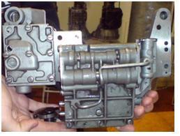
We dissembled the final drive as shown above.
1.         Before any dissembling carried out, I placed a mark with twin on the diff housing caps to make sure they will be reassembled back to its original state.


2.         I didn’t find any identification marks for crown wheel and pinion, therefore I put another two marks with twin, one between the crown wheel and housing and the other the one on the pinion and the flange. I also placed another mark on flange and the diff casing.
3.         After differential caps is removed, I lifted the differential case out the carrier housing out.
The position of the crown wheel is marked on its carrier, therefore we could put the crown wheel back in its original position to ensure it performs well.


4.         After undo the bolts that connect the crown wheel, a chisel is used to remove the crown wheel from the differential casing.


5.         To disassemble the differential pinion and side gears, the pin that is holding the differential pinion shaft is tapped out with chisel.
6.         Once pin is removed, tap the differential pinion shaft a little bit and slid it out.

7.         By rotating both side gears at same time and direction, the pinion gears are exposed and removed. Then other gears are taken out the differential case.
8.         The last part of disassembly is to remove the drive pinion that drives the crown wheel from the differential carrier casing. First, we have to mark the nut in relation to the pinion shaft so later we have to preload the drive pinion when reassembling. To prevent pinion shaft from rotating as we unlock the nut a special tool is shown below to hold onto the drive pinion flange to hold the pinion shaft in position.
 
9.        As the pinion nut is unlock. We tap the pinion shaft with a soft faced hammer while nut is still in position to prevent damaging to the shaft. Once the shaft is loss from the carrier casing, we remove the nut and take out the drive pinion. This completes the disassembling.
Checks and measurements were done while we disassembling the final drive as listed below to ensure that final drive is healthy. Final drive components take huge amount of force while operating and is rotating at such a high speed. If anything is noticeably damaged as visual inspection, further investigation is needed to find out the reason for such damage. Problem causing this damage need to be fixed first and then damaged components need to be fixed or replaced.
l  We visually inspected conditions of all physical components such as broken gear teeth, cracked casing and excessive wearing etc. This final drive passed the visual inspection as there is no faulty found by visual inspection.
l  We measure the run out of the case flange to make sure it is in good contact with the propeller shaft. The measured result is 0 mm which is less the max allowed specification – 0.5 mm. Excessive run out may not only cause drive line to work roughly but also cause damage to the driveline components.


Next thing we did is to reassemble the final drive assembly. It is in the reverse order of disassembly but a little bit more difficult, because not only we have to put everything back but also have to make adjustment according to specification to ensure final drive works properly.   


1.       Before install drive pinion back to the carrier casing, inspect all its components for damage. Apply lubricant to its bearing and treaded surface. Tighten the nut with a torque wrench set to 18 NM. After we reinstall the drive pinion back, we used loaded tester and spring balance to test the tightness of the drive shaft for exercise purpose. Both results show 18 NM.


2.       Check the marking we have made earlier, they should match up by now. Turn the nut about half a turn further to complete the preload process. This extra turning allows the nut to push onto the crushable sleeve. Preload needs to be done is because huge amount of torque will pass the drive pinion when operate, therefore it must be firmly attached to carrier casing otherwise damage will happen. This is the preload process of the drive pinion.


3.       Reassemble the side and pinion gears back to the differential casing. Note the pin that is holding the pinion gear shaft will only go in one way; therefore make sure it is in the right direction. Once reassembled the side clearance are check to ensure there are correct clearance between this gears. The clearance provide space for lubrication and heat expansion. However if it is too large then the gears will have too much space to move the differential wouldn’t work properly. The clearance is adjust with shims. The clearance of side and pinion gears of this final drive are both 0.1 mm which is within specification – 0.05 to 0.2 mm.


4.       Bolt crown wheel back to the differential housing with torque wrench set to 97 NM. Bolts should be tightening progressively in a specified sequence.


5.       Put the differential assembly back to the carrier with crown wheel installed. Refit the caps to the carrier to hold the differential assembly in place. Make sure the thread of the adjuster is lined up with the carrier case and cap thread. Tighten the cap bolts with a torque wrench set to 78 NM.


6.       Checked the radial and lateral run out of the crown wheel both are 0.1 mm, which is same, a specification. Therefore, the crown wheel is not distorted in anyway.


7.       As we did with the drive pinion, we need to preload the carrier bearings to make sure the crown wheel and drive pinion are in good contact and are held firmly inside the housing. Loss one side of the cap and remove it. Put a mark with twink on the bear surface where we could see through the hole in the cap. Refit the cap and bolt it on. Now use the special tool show below to tighten the adjuster until the marking on the bearing just start to move. Now we have completed the preloading process.
8.       Once preloading is complete we need to adjust the position of the crown wheel in relation to the drive pinion, this ensures that the contact between gear teeth of crown wheel and drive pinion are correct.
9.       Bearing blue is used to mark the teeth on the crown wheel. Turn the pinion shaft allow the crown wheel teeth to mesh with drive pinion teeth. We observed from the teeth mark is heavy heel contact. We adjusted the crown away from the pinion and pinion towards the crown wheel to correct this problem. We double checked by measuring the back lash of the crown wheel with DTI the results are all within specification. This completed the resembling process.


       Drive Shafts
       As defined in Automotive Mechanics written by ED MAY – drive shaft is a shaft between the final drive and driving wheel; a shaft between the transmission and the rear axle (Propeller shaft).

The picture below is a shaft between the final drive and driving wheel
In our lab, we mainly looked at the latter one – Propeller shaft which is shown below
As shown in the picture above one side of the shaft is splined onto the output shaft of a transmission and the other end is connected to the flange of the final drive. The splined connection allow the shaft to vary in length. As vehicle is driving on uneven road and the body of the car is moving up and down the distance between the transmission and drive will vary. The yokes on the shaft is joined together by universal joints which also accommodate this problem and also allow shafts to operate at angle according to the road condition. However with this type of design, the York must be installed in correct phasing. When drive shaft is operating at angel the velocity between the front and the end are different. As they are in phase, this difference will cancel each other out otherwise as if they are out phase the car will start to vibrate badly.

In this lab we roughly looked at the following points to ensure correct drive shaft operation
l  Drive line phasing
l  Drive shaft balance
Both of these will cause vehicle to operate roughly. Drive shaft phasing is needed to check the manufacture specification and reinstall the shaft to the correct phasing. Drive shaft balance is check with DTI to look for run out. If it is certain that run out is out specification then balancing is need to be done by adding weights to the drive shaft. This should only be done by specialist.


In this lab we also look briefly at universal joints – cross and York type
The disassembling procedure is described as below
1.         Remove the snap ring under the cup
2.         With one side of the yoke rest on vice, tap the York that is adjacent. This will force the cup to come above the York.
3.         Remove the cup and beware of the needle rollers in it.
4.         Repeat the same for the opposite cup.
5.         Now one yoke is able to come off the joint.
6.         Put remaining York on the vice with freed joint journals rest the vice and tap the York with hammer and force the remaining cap out and remove it.

Th   reassembly is the opposite, just be very careful with the needle rollers as they are very easy to come out. inspections should be done on joint surface condition, caps surface condition , roller condition, seal condition and driveshaft yoke surfaces. For the universal joint we inspected failed the inspection because needle rollers missing. With properly functioning rollers the joint will be worn out in no time. The whole joint need to be replaced. As new joint fitted special care is needed to not damage or loss the needle rollers.

CV   CV joint
       Is the constant velocity joint as in compare the Cross and York type joint, CV joint will provide constant velocity all across the shaft. there are three basic types of CV joint

Birfield Joint
Double offset joint
Tripod joint


General check with CV joints
l  Inspect for split, tears and deterioration in the CV boot. CV joint need to be protected by these boots from dried up or foreign objects. It needs to be lubricated very well in order to functioning properly.
l  Joints must should be checked for play, roughness or binding
l  CV joint components must be checked if there any physical damage.

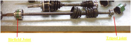
On a drive shaft, the joint that connected to the wheel is called outer CV joint and the inner joint that connects to the final drive is called the inner joint. Outer joint is normally the birfield type and the inner joint is Tripod type.

The outer CV joint could move up, down, left and right direction but it could not move in back and forth direction. The inner joint could however move back and forth quite a lot. The inner joint allows the drive shaft vary in length when car is moving on an uneven surface.

The following is what I did in this lab to disassemble the outer CV joint
1.         Remove the bands that’s hold the boot on to the joint and drive shaft. Move the boot and expose the joint.
2.         This joint didn’t have a snap ring inside therefore I just with a soft faced hammer the joint off the drive shaft
3.         Push the inner ring and cage on one side, remove the ball that’s exposed with a flat head screw driver. Repeat this until all balls are removed.
4.         Turn the inner ring and cage together about 90 degrees. Lift inner ring and cage out of the outer ring.
5.         Turning the inner ring about 90 degree then lift it out of the cage.
6.         Disassembly of the outer CV joint is complete.

The reassembly procedure is the opposite. The tricky part when reassemble is that a pair of special window on the cage needs to be identified before the cage could be put back into the outer ring. This pair is slightly larger than the other ones. Once the larger windows are found, hold the cage vertically and slide the cage into the outer ring. The cage and inner ring should be able to rotate freely inside the outer ring. When try to install the joint back to the drive shaft remember to put the CV boot on. Line the inner ring splines up with the shaft and hit on the shaft on the outer ring to push the joint to go over the clip ring. Care should be taken not to jam the clip ring in between the inner ring and drive shaft. The rest of installation process is quite simple.

To disassemble inner CV joint is quite easy
Remove the bands that is holding the CV boot
Remove the boot
Slide the drive shaft of the housing – spider should be mark in relation to housing, so we could reinstall inner correctly. The disassembling process is completed.
The reassembly is the exact reverse of disassemble.


Automatic Transmission
In our lab exercise we dissembled identified its mechanical parts a three speed manual transaxle of a rear wheel drive vehicle as shown in the diagram below:
As we noticed that this rear wheel drive transaxle does not have the final drive and differential inside. The final drive and differential is connected to the transaxle with propeller shaft, which is connected to the output shaft of the transaxle. The reason we used the transaxle shown above is due to its simplicity that will give us a better understanding of automatic transmission as beginners.

First thing we did is as usual we dissembled this transmission shown above, inspected and identified its mechanical components and then resembled everything back to its original state. Dissembling process of this automatic transmission is not as hard as the manual transmission we have done previous. I think this is probably because it didn’t use many physical gear shift mechanisms; instead a hydraulically operated valve control body is used. Eventual the physical appearance of this automatic transmission but as it is using hydraulic controls and planetary gears – its operation is somehow seems to be much more complicated than manual transmission we done before. This is because its operation is a lot more abstract, we cannot understand how it works until we studied the theory behind its operation. To understand how automatic transmission there two important parts we have to understand:
Its mechanical parts – this includes clutch, bands and gearing etc.
Its hydraulic control system – the components inside the valve control body or the brain of this transmission.

We dissemble this transmission in the following order
1.       Turn the transmission over as shown.
1.       Remove its oil pan to expose some of its components.
1.       Valve body removed

As valve control is removed, more components revealed.
1.       Servos are then removed, now we could sea the components more clearly.
1.       Front Clutch, Rear Clutch, Front Band are then removed. With the rest of the component we have to start from the output side of the transmission. First we have to remove the output extension housing.
1.       Slide governor and oil pump off from the output shaft.
1.       Then the rest of the transmission components are taken out from the back and dissembling is completed. The resembling procedure is the exact opposite.


Transmission is used to control the torque output from the engine to the drive line to drive a vehicle according to the gear selected, therefore the output is controlled according to the condition. In a manual transmission gear selection is done by the driver where as this is done by mainly by valve body control in this automatic transmission we have studied in this lab exercise. There are two parts we have to look at as listed below:
l  The mechanical part
l  Hydraulic Control
The mechanical parts
This is the gears, Clutches and bands layout of the transmission we took apart

A simplified diagram shown below shows all major components control the gear ratio or the right amount of torque going to the driveline to drive a vehicle:

The automatic transmission output is varied by means of gearing same as with manual transmission. Gear ratio is varied by the size of a driver gear in relation to its driven gear. When a small gear is driving a larger gear, the output torque will increase but speed of output rotation will decrease. When a larger gear drives a smaller gear, the opposite will happen. The particular transmission we worked on is using a planetary gear set to achieve desired gear ratio. The planetary gear set of this transmission is shown below:
By rotating certain gears while holding some other gears constant the final output the transmission will be altered. For example the first gear ratio is achieved by rotating the primary sun gear and hold the carrier stationary. As the engine turns the primary sun gear, sun gear shall drive the pinion gears, which will in turn rotate the secondary pinion. As the carrier is held stationary there will be no planetary action involved, the secondary pinion will pass the rotation to the ring gear to provide the final output. The primary sun gear is this case is the driver and the ring gear is the driven gear. Since ring gear or internal gear is a lot bigger in size, a high gear ratio is obtained. With high gear ratio the output torque will increase with lower speed. This is only one example, for other gear ratio different combinations but all rely on the same principle.

The following mechanisms are used to vary gear ratio by this particular transmission
l  Front Clutch is connected to the input shaft. it will connect the primary sun shaft when applied therefore drive the primary sun gear.
l  Rear Clutch and the secondary sun gear is actually one piece. When applied it will hold onto the front clutch which connected to the input shaft all the time. Rear clutch drives the secondary sun gear.
l  Front band is used to hold the secondary sun gear constant.
l  Rear band is used to hold the carrier constant.

The different output gear ratio is shown in the table below
Gear
Applied
Applied
First
Front Clutch
Rear Band or OWC
Second
Front Clutch
Front Band
Third
Front Clutch
Rear Clutch
Four
Rear Clutch
Rear Band

When to apply Clutches and bands are determined hydraulically inside the valve control body.
Valve control body is acting as the brain of the transmission. It contains a lot of valves which is similar to on and off switches and they are operated hydraulically. The basic operation of hydraulic control system is described below:

Oil sucked into the oil pump though a passage in the valve body from oil pan. Then pressurized oil is pumped from the oil pump enters the valve body through another passage to be distributed to other parts of the hydraulic system.

Before this the pressured fluid entre into another part of the system, it has to pass through the primary regulator. Only regulated line pressure is allowed to enter to the rest of the system. Some oil is returned to the oil pan as result through the exhaust. Both line and convertor pressure are varied by modulator valve according to governor and throttle pressure.

However before the fluid could actually pass the primary regulator and where it is allowed to go is determined by a main valve which is called the Manual Valve which represents driver’s will. This valve allows driver to select 1 , 2, 3, R, N and P. Now let assume driver selected 3 and the line pressure is passed into the system.

Line pressure should now reached to Shift valves – these valves are controlled by governor and throttle pressure. As in low speed line pressure is blocked by 1-2 shift valve until speed is high enough, governor pressure will then be able to overcome the throttle pressure push 1-2 shift to unblock the line pressure therefore 2-3 shift valve can work. Once gear is selected clutches or bands will be applied or released. Note bands are applied through servos. Throttle Valve – Commonly connected to the acceleration pedal with a cable. Throttle pressure is applied directly to the oppose end of the governor pressure. This valve tries to keep transmission in low gear. Throttle pressure represent the engine load. The throttle pressure also could increase the system line pressure as it is directed to the primary regulator as well. This is very important when vehicle demands more torque.

There is a special condition called kickdown which is handled by a kickdown valve. It is only activated on full throttle. It allows throttle pressure goes from a special kickdown passage to directly causing gear to downshift.

As explained above this is how a hydraulic control system work. Before I finish off here there is just one more thing I should explain which is the secondary regulator valve - – as the torque converter requires a different pressure than most other parts of the system, fluid is directed into secondary regulator to be converted to converter pressure after the fluid passed the primary regulator.

Manual Transmission
Specifications of transmission we inspected are listed below
Toyota 5 speed manual transaxle
Model C50, C51, C51 and C150

The disassembling procedure is as follow
1.       The rear recover is removed to expose fifth gear.
1.       Shift nut is removed while input shaft is held constant.
2.       Fifth gear synchronizer, fork and gears are removed. The gears need special puller to remove and c clips need to be removed before pull gears. Special care need to be taken not to damage the gears teeth while pulling them off.
3.       Before removing the transaxle casing, detents has to be removed with care. Detent balls and springs are very easy to be lost.
4.       Transaxle case is removed. Shafts, gears, Shift mechanisms are all exposed
1.       Shift mechanisms are removed.
1.       Input, output and idler shafts are removed.
2.       Final drive ring gear and differential are lift out the transmission casing. Dissembling completed
The reassembling procedure is exactly the reverse of disassembling. However two things are very important to be remembered:
1.       Before putting transmission casing back, make sure the shift rails are correctly installed so the detents could be fitted in.
2.       When putting back the fifth gear special pressing tool will be needed. Don’t forget to put circlips back.

The basic structure of this transmission is shown in the diagram below
The torque from the engine is not directly transmitted to the drive line to drive the vehicle instead torque from the engine is first transmitted into the transmission. The transmission will then vary the torque according to the driver’s decision. The torque may be increased or decrease by the transmission before goes into the drive line. Torque is varied by means of gearing. 

The basic operation of C50 is described below with our testing results:
The torque from the engine flows into the transmission through the input shaft. Then flow out the differential which is connected to the output shaft into the drive line.
There are six gears on the input shaft as shown in the diagram. These gears are 1 – 5 and the sixth gear is the reverse gear. These gears are called driver gears because the torque flows from these gears will drive their mating gear on the output shaft. On the output shaft there are also six gears which are driven gears and they are constantly in mesh with their driver gears apart from the reverse gear. Transmission with this type of gear arrangement is called SYNCHROMESH TRANSMISSION. The advantage of this type of arrangement is easier gearshift and minimizes gear wearing. Gears 1, 2, 5 and reverse on the input shaft are integral to the shaft. Gears 3 and 4 are freely spinning on the input shaft. The mating gears on the out put shaft are exactly the opposite apart from the reverse gear. Gear 3, 4 and reverse is integral to the output shaft. 1, 2 and 5 are freely spinning. Reverse gears don’t touch each other. They are connected by an idler gear which only connects them when selected.

Both input and output shaft is placed on bearings on both ends – cage roller in the front and ball race at the back to handle rotation. The final drive is using tapered bearings which are much stronger and provide support on both horizontal and vertical movements. All constant but removable gears on the shaft are fitted with needle bearing which are also aimed to handle end thrusts as well. All shafts, gears and bearing are visually inspected and are free of scores, wears or any other physical damages. All bearings are also rotating freely.

Power will only flow through the driver and driven gear when the free spinning gear is holding constant by the synchronizer. The following diagram show the power flow when first gear is selected.
Synchronizer A is shifted to the right to select gear 1 on the output shaft. This will hold the driven gear 1 to the output shaft. Therefore transfer power from the engine to driver gear 1 which is part of the input shaft, then from the driver gear 1 to driven gear 1 to rotate the output shaft.
All other gears won’t be able to provide passage for the power flow. Driver gear 2 is rotating as it is part of input shaft but the driven gear 2 is freely spinning. Driver gear 3 and 4 are free spinning on the input shaft therefore they cannot drive the driven gears. Driver gear 5 is connected to the input shaft but its driven gear is freely spinning on the output shaft. The other four forward gears work the same. Each synchronizer controls 2 gears. A controls gear 1 and 2, B controls 3 and 4, C controls 5 and reverse.

The reverse gear is somehow different. It is not a synchromesh type gear, instead it is a sliding engaged gear. It has a third gear – idler gear on a separate shaft. Driver reverse gear on the input shaft is part of the shaft. Driven reverse gear is actually the synchronizer A as shown in the first diagram. These gears are not in contact with each other. When the reverse is selected, the idler gear moves up to engage both reverse gears on the input and output shaft. The function of this third gear also reverse the direction of the rotation therefore reverse the vehicle.

Notice when synchronizer C is moved to the left to select reverse the idler gear is moved up connected driver and driven reverse gear. The power from the engine is flowing through the driver reverse gear to the idler gear. From the idler gear is then flowing to the driven reverse gear therefore rotate the output shaft in opposite direction.

An important thing should be noticed is that reverse gears are not helical gears as all other forward driving gears. They are using spur gears with straight teeth. Spur gear is not as strong or durable as the helical gear. However it is quite suitable for reverse operation. As a sliding engaged gear it made the design much easier than if using helical gears. However due to the fact it has much less contact area when engaged, reverse operation shouldn’t be done over long period of time or at high speed as the spur gear might get damaged.
As we looked at the gears on the input and output shafts we can see that driver gear and its mating gear are normally in different sizes. This is how the transmission varies the torque coming from the engine with gear ratio. Gear ratio is calculated as driven gear teeth number over driven gear teeth number. Therefore with higher gear ratio the output torque will be increased and speed will be decreased. As the gear ratio decreases the opposite will happen.

The following table shows the number of teeth of each driver vs driven gear and their gear ratio
Gear
Driver teeth
Driven teeth
Gear ratio
First
12
38
3.2
Second
21
40
1.9
Third
24
38
1.6
Fourth
33
33
1
Fifth
31
38
1.2
Reverse
12
39
3.3
Final Drive
17
69
4.1
First gear has the highest gear ratio amount all forward driving gears so it output largest torque with least speed. Fourth and fifth gear have much lower gear ratio therefore they output much less amount of torque but have higher speed therefore could lower the engine rpm when cruising.  

A striped down synchronizer is shown below


The inserts are fitted onto the slots on the hub and hold by springs. The hub has splines in the center which hold the hub onto the shaft. The sleeve holds onto the hub. The sleeve has splines inside which can slide on the hub. When sleeve is pushed by shifting fork, it slides towards the selected gear. As the sleeve moves it takes the inserts with it. Inserts pushes baulk ring forward. The baulk ring has a corn inside which will contact with the corn on the selected gear. Baulk ring will try to either decrease or increase the rotating speed of the selected gear. This action will synchronize the speed of selected gear and the synchronizer. Before the speed is synchronized the baulk ring will also block the sleeve to prevent the sleeve trying to engage with the selected gear therefore damage the gear or synchronizer itself. As the baulk is synchronizing the speed, it will be dragged by the selected gear half a teeth outline with the sleeve. Maximum amount of dragging is limited by the insert inside the recess of the baulk ring. Only when the sleeve and gear are synchronized, sleeve will be able to slide over the baulk ring and slide onto the gear dog teeth. Selected gear will then be connected to the shaft by the synchronizer and moves with the shaft as one.
The gear shifting mechanism for this transmission is very similar to the diagram above. Gear shifting contain two actions
Select gear rail
Selector lever will allow driver to select the shift shaft – each shaft controls one synchronizer therefore two gears.
Shift the gear
Once synchronizer is selected then shift lever is used to select one of two gears which is controlled by that synchronizer.

To prevent more than one gear is selected at same time ball type INTERLOCK mechanisms are used inside the housing of shift shafts. As one shift rail is selected the other two rails are blocked. This transmission also uses a interlock plate as shown which only allow control finger to act on one shift rail at a time, as the other two are blocked by the interlock plate.

This transmission also used detent mechanism to prevent jump out gear and also hold gears accurately in their correct position. Detent balls are pushed into the grooves on the shift shafts to hold shafts in position.